In this tutorial, we will discuss what UART communication is and how it works. We will also write a simple sketch to show how to use the Arduino Uno’s UART interface. Then we will demonstrate with a project that uses UART to communicate between two Arduinos.
What is UART?
UART stands for Universal Asynchronous Receiver/Transmitter. It is a hardware device (or circuit) used for serial communication between two devices.
How are UART Devices Connected?
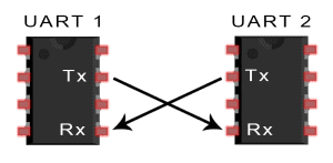
Connecting two UART devices together is simple and straightforward. Figure 1 shows a basic UART connection diagram.

One wire is for transmitting data (called the TX pin) and the other is for receiving data (called the RX pin). We can only connect two UART devices together.
How does UART Work?
UART works by converting data into packets for sending or rebuilding data from packets received.
Sending Serial Data
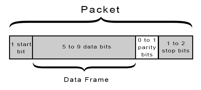
Before the UART device can send data, the transmitting device converts the data bytes to bits. After converting the data into bits, the UART device then splits them into packets for transmission. Each packet contains a start bit, a data frame, parity bit, and the stop bits. Figure 2 shows a sample data packet.

After preparing the packet, the UART circuit then sends it out via the TX pin.
Receiving Serial data
The receiving UART device checks the received packet (via RX pin) for errors by calculating the number of 1’s and comparing it with the value of the parity bit contained in the packet. If there are no errors in transmission, it will then proceed to strip the start bit, stop bits, and parity bit to get the data frame. It may need to receive several packets before it can rebuild the whole data byte from the data frames. After rebuilding the byte, it is stored in the UART buffer.
The receiving UART device uses the parity bit to determine if there was a data loss during transmission. Data loss in transmission happens when a bit changed its state while being transmitted. Bits can change because of the transmission distance, magnetic radiation, and mismatch baud rates, among other things.
UART Parameters
UART has settings that need to be the same on both devices to have proper communication. These UART settings are the baud rate, data length, parity bit, number of stop bits, and flow control.
Baud Rate
Baud rate is the number of bits per second (bps) a UART device can transmit/receive. We need to set both UART devices with the same baud rate to have the proper transmission of data. Common values for baud rate are 9600, 1200, 2400, 4800 , 19200, 38400, 57600, and 115200 bps.
Data Length
Data length refers to the number of bits per byte of data.
Parity Bit
The parity bit is a bit added to the transmitted data and tells the receiver if the number of 1’s in the data transmitted is odd or even. The possible setting for Parity Bit is Odd or Even.
- ODD – the parity bit is ‘1’ if there is an odd number of 1’s in the data frame
- EVEN – the parity bit is ‘0’ if there is an even number of 1’s in the data frame
Number of Stop bits
UART devices can use none, one or two stop bits to mark the end of a set of bits (called packets) transmitted.
Flow Control
Flow Control is the method to avoid the risk of losing data when transmitting data over UART. The UART device uses special characters as flow control to start/stop transmission.
Arduino UART Interface
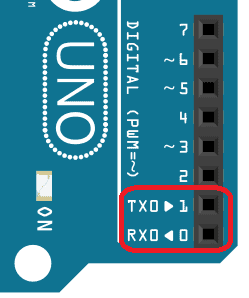
Arduino has one or more UART pins depending on the board. For our project, we will use an Arduino Uno which has only one UART interface found on pin 0 (RX0) and pin 1 (TX0). The Arduino pins 0 and 1 are also used for communicating with the Arduino IDE via the USB. So if you will upload sketches to your UNO, be sure to first disconnect any wires on pins 0 and 1. Figure 3 shows the location of the UART TX and RX pins.

UART Logic Level
The UART logic levels may differ between manufacturers. For example, an Arduino Uno has a 5-V logic level but a computer’s RS232 port has a +/-12-V logic level. Connecting an Arduino Uno directly to an RS232 port will damage the Arduino. If both UART devices don’t have the same logic levels, a suitable logic level converter circuit is needed to connect the devices.
For further reading about UART, please check out our article on the Basics of UART Communication.
A Simple UART Project
After learning how the UART works, let us now build a simple sketch demonstrating how to use UART communication using Arduino Uno.
Our project is about controlling the built-in LED of an Arduino remotely via UART. A push-button wired to the first Uno board will control the built-in LED of the second Uno board and vice versa.
Components Required
To build our project, we need the following components:
Connection Diagram
Figure 4 shows how to connect the components used in our project.

If you want to learn more about the Arduino, check out our Ultimate Guide to the Arduino video course. You’ll learn basic to advanced Arduino programming and circuit building techniques that will prepare you to build any project.
Arduino Sketch
After gathering and assembling the hardware, we are now ready to program our boards. For this project, both boards will have identical sketches. First, we set pin 8 (push button) pin mode to INPUT_PULLUP, set pin 13 (LED) pin mode to OUTPUT and set the initial state of pin 13 to LOW (LED off).
void setup() { pinMode(8, INPUT_PULLUP); // set push button pin as input pinMode(13, OUTPUT); // set LED pin as output digitalWrite(13, LOW); // switch off LED pin}void loop() {}Serial Object
As always, the Arduino makes it easy for us to use the built-in UART hardware by using the serial object. The serial object has the necessary functions for an easy use of the Arduino’s UART interface.
Serial.begin()
To communicate via the UART interface, we need to configure it first. The easiest way to configure the Arduino’s UART is by using the function Serial.begin(speed). The speed parameter is the baud rate that we want the UART to run. Using this function will set the remaining UART parameters to default values (Data length=8, Parity bit=1, Number of Stop Bits=None).
If the default settings don’t work for you, use the function Serial.begin(speed,config) instead of Serial.begin(speed). The additional parameter config is used to change the settings for data length, parity bit, number of stop bits. Defined values for the parameter config can be found here.
The code below adds Serial.begin(9600); inside setup() to initialize the Arduino Uno UART with a baud rate of 9600 bps and other parameters set to default values.
void setup() { pinMode(8, INPUT_PULLUP); // set push button pin as input pinMode(13, OUTPUT); // set LED pin as output digitalWrite(13, LOW); // switch off LED pin Serial.begin(9600); // initialize UART with baud rate of 9600 bps}void loop() {}The next part to code is to read and save a value received from the serial. To do this, we will use the function Serial.available() together with an If statement to check if there is data received. We will then call Serial.read() to get one byte of received data and save the value to the variable data_rcvd. The value of data_rcvd controls the On/Off of the built-in LED.
Serial.available()
To check if there is data waiting to be read in the UART (or serial) buffer, we will use the function Serial.available(). Serial.available() returns the number of bytes waiting in the buffer.
Serial.read()
To read the data waiting in the serial buffer, we will use the function Serial.read(). This function returns one byte of data read from the buffer.
void setup() { pinMode(8, INPUT_PULLUP); // set push button pin as input pinMode(13, OUTPUT); // set LED pin as output digitalWrite(13, LOW); // switch off LED pin Serial.begin(9600); // initialize UART with baud rate of 9600 bps}void loop() { if(Serial.available()) { char data_rcvd = Serial.read(); // read one byte from serial buffer and save to data_rcvd if(data_rcvd == '1') digitalWrite(13, HIGH); // switch LED On if(data_rcvd == '0') digitalWrite(13, LOW); // switch LED Off }}Serial.write()
For us to send data via Arduino’s TX0 pins, we will use the function Serial.write(val). The val parameter is the byte (or series of bytes) to be sent.
In our sketch, we will send a char value depending on the state of pin 8. We will send the char value of '1' if pin 8 is HIGH or a char value of '0' if the pin 8 is LOW.
void setup() { pinMode(8, INPUT_PULLUP); // set push button pin as input pinMode(13, OUTPUT); // set LED pin as output digitalWrite(13, LOW); // switch off LED pin Serial.begin(9600); // initialize UART with baud rate of 9600 bps}void loop() { if (Serial.available()) { char data_rcvd = Serial.read(); // read one byte from serial buffer and save to data_rcvd if (data_rcvd == '1') digitalWrite(13, HIGH); // switch LED On if (data_rcvd == '0') digitalWrite(13, LOW); // switch LED Off } if (digitalRead(8) == HIGH) Serial.write('0'); // send the char '0' to serial if button is not pressed. else Serial.write('1'); // send the char '1' to serial if button is pressed.}Sketch Upload and Testing
Save the sketch as arduino_uart_tutorial.ino. The remaining step is to upload the sketch to both Arduino Uno boards. Please remember to disconnect the wires connected to TX0 and RX0 pins before uploading the sketch. After uploading successfully, reconnect the wires on TX0 and RX0 pins.
After uploading, we can control the built-in LED of one of the boards by pressing the push button connected to the other board. Our sketch checks the button state and sends a corresponding char value of'0' or '1' to the other board to control the built-in LED.
Be sure to leave a comment if you have any questions or have trouble setting this up!
